
For our discussion of Electrical Theory we will start with a simple example and see what happens as we apply some modifications to the base setup.
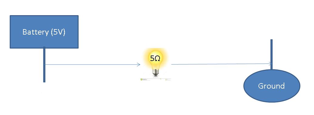
Above we see a simple circuit lighting the bulb in the middle. We can see that the battery guarantees 5 volt output, and the bulb has an inherent resistance to current of 5 Ohms (symbolized by the Greek letter Ω). In the following examples, we will seek to answer the following questions:
- How much power is drawn by components?
- How much current is flowing from the battery?
Before we can continue a brief description of each component may be useful.
- Battery – The battery acts as a fixed voltage source for our bulb. Regardless what happens in a given circuit, the voltage at the battery will be 5 relative to ground.
- Ground – The ground acts as the sink for a given circuit and marks completion of a given path. We distinguish the ground as 0 and set voltages of other components relative to this (ex: the battery is 5 Volts relative to ground).
- Bulb – The activate component in the circuit. We know before this element there is 5V and after there is 0V. Therefore this component must be taking some energy from the system.
In the above diagram, we have information on the following attributes:
- Source Voltage – A measure of how much potential for work a given element has.
- Resistance – A description of how much some component resists current.
The resistance of a given component can be calculated by dividing the Voltage by the Current passing through the component. This leaves us with the following formula for describing a simple circuit:
Resistance (Ω) = Voltage (V) / Current (A)
Note: In this context, the Resistance can be seen as constant conversion between Voltage and current (V = ΩA).
In a circuit, charge flows from a point of higher concentration (voltage source) to a point of lower concentration(ground). This movement provides some energy which can be used to power applications such as the light-bulb from our example. From this we can see that Power is related to both the voltage and how much current is flowing over the voltage.
Power (P) = Voltage (V) * Current (A)
Great! Now we have all the components we need to solve our original question!
A = (V/Ω) = 5 / 5 = 1 Amp drawn from the battery.
P = VA= V *(V/Ω) = V²/Ω = 5²/5 = 5 Watts drawn from the bulb.
Next, let’s look at a Parallel Circuit to see the impact of connecting multiple elements to a given battery.
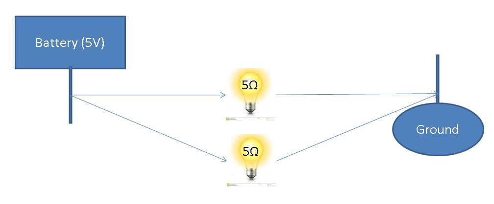
Above we see the same diagram with the addition of another bulb on a different path from the original bulb. This is referred to as a parallel circuit.
When looking at each bulb in isolation, we expect the problem to be the same as our original example. And it is! Given the battery can supply an arbitrary current, we will see each bulb draws the same 5 Watts as it did in the base case. The primary difference is now we have 2x the draw on the battery (2 Amps drawn at the battery with 1 Amp flowing over each bulb).
How much power is drawn by components?
Same as the base case!
How much current is flowing from the battery?
2x the current draw on the battery.
Formalization: For a parallel circuit, each branch can be handled in isolation and the total current draw is the sum of the parts.
Finally, lets look at a Series Circuit to see the impact of connecting multiple components to each other.

Above we see the same diagram with the addition of another bulb attached to the output of the original bulb. This is referred to as a series circuit.
When looking at the above, we can’t help but wonder if replacing the above bulbs with a single 10Ω bulb would be a valid reduction. And it is! One way to reason this is to focus on an individual particle going through the wire. If we consider the resistance to be the amount of time the particle is in the component, stacking 2 of the same component will increase the time spent 2x.
Formalization: To calculate the voltage drop across each component, we can look at the proportion of voltage left after each component as follows:
5 V -> (5/10 Potential Used) – 2.5 V Remaining -> (5/10 Potential Used) -> 0 V Remaining
How much power is drawn by components?
P = VA= 2.5 * 0.5 = 1.25 Watts drawn from each bulb. (2.5 Watts drawn total)
How much current is flowing from the battery?
A = (V/Ω) = 5 / 10 = 0.5 Amps drawn from the battery.
Discussion:
In this section, we discussed simple circuits consisting of sources, power-drawing components, and grounds. We have seen how the layout of a given circuit can have significant implications for both functional behavior and power consumption. We have also looked at some aspects of circuit reduction.
While these are simple cases, the above forms of circuit analysis lay the foundation from which we can begin to look at the design of more complex circuits. Providing power to components, understanding the load each component will place on the circuit as a whole, and reducing complexity are requirements as we strive for faster and more efficient processors.
In particular, the question of how to reduce power consumption of processors has become an active area in recent years. In the above section we spoke of using circuits to perform work. One byproduct of work is the generation of heat and as the size of processors decreases, the harmful effects this has on both the integrity of circuits and the total cost of operation becomes more pronounced (For more information, see Heat Wall – Section 3.A).
This hardware bottleneck, along with the ever-lowering cost of existing processors may have led to the boom in multi-core and a more widespread adoption of functional programming paradigms.
But this, we will get into later.
