
In prior discussions, we have seen how modifying inputs of a circuit can influence the outputs. In today’s discussion we will explore another influence, time. We will begin our discussion with an example.
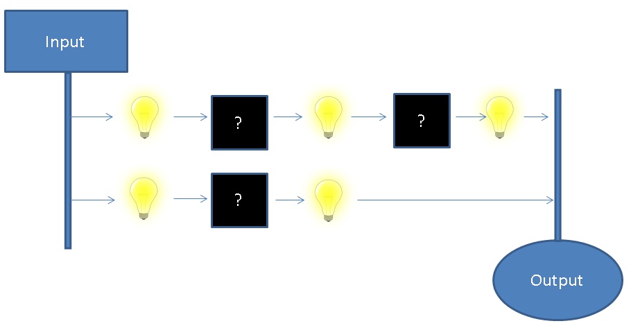
In the above example, we have 2 inputs travelling through some hidden components. After each “black box, ” we have a light connected to show whether the value is set, or unset. In addition to the above visualization, let’s add 2 “rules” for the above circuit and see how it behaves.
- Both inputs will always have the same value (On or Off)
- Both outputs will always match the inputs™
In it’s initial state, everything seems fine. But what happens if we modify the inputs?
As we can see, the lower signal reaches the output before the upper signal. This means that the circuit state is invalid for some amount of time whenever an input is updated. While the actual delay is significantly increased in this example, the real delay can be just as significant on the timescale computers operate on. How can we go about solving the problem of circuit propagation delay?
- Add some “delay” black box on the lower signal. While “simple,” each black box must be tailored to the dependent circuitry. Also, this may waste a significant amount of what could be utilized space.
- Define some amount of time a given signal path must be completed in. Make sure no signal path takes longer than this amount of time, and hold onto completed results until the specified time is elapsed.
Option 2 is the basis from which the processor clock is derived. By structuring circuits around a clock we can prevent the output from seeing invalid states, maximize utilization of available space, and reduce the complexity of circuit integration. 
Great! Now that we understand the benefits of storage in more complex circuits, we can begin to look at how. Conceptually, we have 2 ways of doing this.
- Find a component which is capable of physically holding onto the input (DRAM).
- Introduce some circuitry which can hold onto given state. Include a way to associate this state with the input (SRAM).
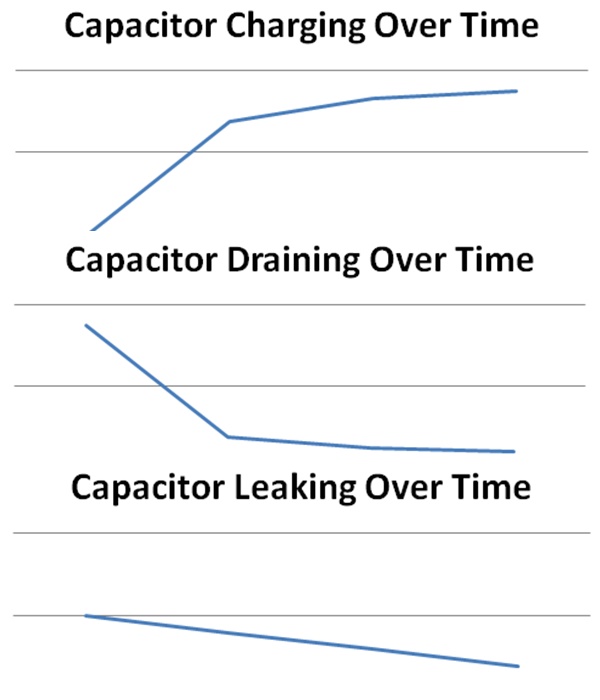
Of the two, DRAM may be more intuitive. DRAM holds current state for future use in a physical component called a capacitor. The behavior of a capacitor is such that if the input has some voltage, the voltage at the capacitor will increase over time. When drained, the voltage at the capacitor will decrease to 0 over time.
The benefit of DRAM comes from its simplicity. 1 capacitor is 1 storage cell. Because of this, DRAM can be more cost-efficient to include in circuits. There are 2 drawbacks to DRAM.
- Charge/Drain time – The time to charge/drain a capacitor means there is a delay in storing data in any given cell, this increases write time to a DRAM cell.
- Capacitor Leakage – Over time, storage in the capacitor may leak meaning there must be infrastructure established to ensure periodic refreshes (or risk invalid state). This means an individual DRAM cell is a constant power draw.
Unlike DRAM, SRAM has 2 inputs. A “set” input and a “unset” input. SRAM behaves as follows:

In our discussion on The Building Blocks of Processors, we touched on the capacity to model Boolean logic as a circuit. Already we are starting to see applications! The Flip-flop article on Wikipedia has some great diagrams of implementations of SRAM storage cells using representative logic gates.
SRAM removes the issues associated with the usage of capacitors in DRAM at the cost of increased circuit complexity. Whereas a single DRAM cell will typically consist of 1 capacitor, a SRAM cell will typically be built from 4 transistors. Because of this, SRAM is reserved for applications where the performance hit from using capacitors will be most expensive (closer to the processor).
Discussion:
In this section, we had a discussion about the reasons for introducing state into circuitry, and 2 ways this state can be embedded into a given circuit. One segment we skipped over in this section is a discussion of what exactly this stored state is. Computers will typically use voltage as the analog representation of a digital bit. For example, in the above SRAM table, the True segments correspond with high voltage, and the False segments correspond with low voltage. One question to consider at this point is: Why not use current instead of voltage?
Using voltage instead of current provides some benefits that make it preferable to using current as the representation of a digital bit.
- Lower power consumption – We can prevent significant current from flowing through a given circuit. Because all wires have inherent resistance, current flow can be expensive.
- FET’s (ex: MOSFET) are voltage controlled. When almost every transistor in a computer is voltage controlled, it makes sense to keep everything consistent.
